I will be using non-technical language. I presume those who need learn this skill would be frightened off by a technical discussion. I also presume those who know the technical language also know how to make cables already. I hope this will be simple enough that anyone can now make their own cables.
Here are the problems you will encounter:
There are three kinds of crimping tool: hand held, bench mount and powered. The hand held unit is cheapest. You can take it with you to a jobsite. The bench mount has a lever to pull to crimp. This takes less strength. Because it is mounted, it is also easier to work with. The power models are for cable factories.
The problem is every manufacturer of connectors makes them a slightly different size. If for example you use an AMP crimping tool on Robinson Nugent connectors, it will just crumple them. You need a special die for each brand and size of connector. AMP, of course, does not sell any dies, except for AMP connectors. Conversely if you used AMP connectors in Robinson Nugent dies, they would flop around and you would not get good alignment.
Before you buy a crimping tool, make sure dies are available for all the connectors you plan to use. When you budget in all the dies, the costs can be rather disconcerting. Sometimes your favourite brand of connector may be out of stock. If you don’t have a die for the replacement, you are in trouble.
Making Ethernet Ten Base T RJ-45 cables (and by extension, RJ-11 and RJ-14) it’s not hard but it does require a crimp tool. Crimp tools for RJ-45/11/14 can be had cheaply, or you can get a decent one. David Charlap got a fairly good one made by Ideal at his local Home Depot. The ratchet/handle cost and the die for RJ-45 cost . A die for RJ-11/14 also costs about
 I like 3M brand or
Amphenol Spectra
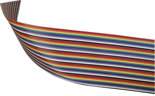
Strip (discontinued?) ribbon cable. It is rainbow coloured which I find
makes it much
easier to use, especially when it comes time to count the conductors to
make twisted
floppy cables. When they are all grey, my eyes just give up. The
conductors are
tinned copper. The tin helps prevent the copper from tarnishing.
I like 3M brand or
Amphenol Spectra
Strip (discontinued?) ribbon cable. It is rainbow coloured which I find
makes it much
easier to use, especially when it comes time to count the conductors to
make twisted
floppy cables. When they are all grey, my eyes just give up. The
conductors are
tinned copper. The tin helps prevent the copper from tarnishing.
Because Spectra Strip is thicker, you need connectors with sharper teeth to puncture the insulation. If your cables don’t work, it may be that the connector teeth are not sharp enough. Those sorts of generic connectors only work on the thin grey cables.
For SCSI you will need a single 50-conductor cable with multiple drops. For wide SCSI (SCSI-3) you will need a single 68-conductor cable. SCSI will let you attach up to 7 devices on a single cable, including hard disks, CDROM (Compact Disc Read Only Memory) s, scanners and tape backup units.
For external SCSI devices, you are best to buy pre-made round cables. Unfortunately with external SCSI devices, there are three common different types of connector. You must daisy chain from device to device with a separate cable ensuring each leg has the needed connectors on each end. These cables are horrendously expensive so make sure you get the right kinds and lengths.
For EIDE or IDE (Integrated Drive Electronics), you will need a single 40-conductor cable. These let you attach hard disks and CD-ROM (Compact Disc — Read Only Memory)s. You can attach two devices (master and slave) to the primary channel. In machines with a secondary channel, you can attach a second master/slave pair of devices on a separate cable.
For an MFM, RLL or ESDI (Enhanced Small-Device Interface) system, (now obsolete), you will usually be building three cables. You need some 34 conductor cable (for the floppy cable and the wide hard disk cable) and some 20 conductor cable for the narrow hard disk cable. If you are buying just enough for one set of cables, buy three times too much to give yourself a chance to goof up. By Murphy’s law you will get it right the first time. However, if you follow my advice about paper mockups you have a good chance of making it on your first try.
Buy plain flat cable. The braided stuff will be harder to handle. Take a sample set of cables with you when you go to buy the parts. It is quite legit to just point and say — I want some of that only in rainbow colours and more flexible.

I have not seen this product for sale. If anyone knows of something like this, please let me know. It consists of pairs of tiny coloured dots. They would come in a package containing a wide selection of bright rainbow colours. You need to be able to find a pair in a colour to contrast with any background. You could use them in pairs if there were not sufficient unique colours for a given job. They might be made of plastic, vinyl, glass, ceramic or special type of paint with high surface tension that pulled itself into a perfectly round blob. You could stick them to any surface including metal or vinyl, perhaps using a dot of special glue. They must not come off with water, alcohol or common solvents. The Avery coloured dots you get an a stationery store come off far too easily. They are designed to stick only to paper. You want them to look neat, as though they were part of the original equipment. You don’t want a crude slash of nail polish. They need to stick to both flat and curved surfaces. You would use them for example to mark pin 1 of a connector and pin 1 of a socket. You can mindlessly match them up to reconnect a computer getting all the connectors in the right place right way up. They could be used for external cables as well. They could also be used on stereo equipment or anything else with multiple cables. Since manufacturers won’t shape-colour code connectors for economic reasons and since sometimes connectors don’t have a dedicated purpose, this is the next best thing. If you are a company considering producing such a product, you could also sell it as a child’s toy, something to decorate toys or other objects, though the child’s toy version probably should have a non-permanent adhesive.
I like 3M brand or Amphenol Spectra Strip ribbon cable. I have had success with Amphenol and RN (Robinson Nugent) brand. You want ones with some gold plate — that is the reason we are going through this exercise — to get good contacts.
AMP connectors have barbs on the teeth to prevent the wires from pulling out. Amphenol (no relation to AMP) has little release triggers to let you open up a connector. Remember, your crimping tool must match your connector brand.
If you are buying large quantities, ask the manager for a deal.
You can buy prefabricated cables on the web from
| Screwdriver and Screw Types | ||
|---|---|---|
| Appearance | Name | Notes |
 |
slot head | Also known as flat blade. Used in AC (Alternating Current) electrical wiring and consumer products. Screw slot slips easily. Invented by nameless British carpenter in 1744. |
 |
Phillips | Commonly misspelled as Philips. Also known as cruciform. Used in computer cases and AC electrical wiring. Most common on smaller screw sizes. You will need both American and metric versions. Most common sizes are Ph0 to Ph3 with #0 being the smallest. Screw less likely to slip that slot head. Invented by American Henry F. Phillips in 1936. |
 |
Posi-Drive | aka PoziDrive. Used in ski equipment and on euro-hinges in cabinetry. Similar to Phillips. Comes in sizes Pz0 through Pz2. I don’t know the inventor. |
 |
Robertson | Also known as square-tip. Used in furniture and in Canada. Screw can be held firmly on the tip of a screwdriver. Most common an mid and larger screw sizes. You can put quite a bit of muscle on the screw without it slipping. Handles are usually colour coded for size: yellow(#0), green(#1), red(#2), black(#3) and double black(#4), with the smallest being yellow(#0) and green(#1) and red(#2) being most common. Invented by Canadian Peter Lymburger Robertson in 1908. |
 |
Torx 5 lobe | Tamper-proof applications. Screwdriver sales of variant proprietary secure designs are restricted to registered equipment owners. |
 |
Torx 6 lobe | Tamper-proof applications. In Macintosh and Compaq computer cases and automotive. This keeps out the casual user. Typical sizes include T-8, T-9, T-10, T-15, T-20, T-25. Also used for various proprietary secure variants that restrict the sale of screwdrivers to registered equipment manufacturers. The actual lobes look more gear-like and less flower-like than my illustration. |
 |
Allen key | In furniture designed to be assembled by the customer and then disassembled later, especially that sold by Ikea. Works with an L-shaped wrench often included with the furniture. You will need both American and metric versions. Invented by American G.F. Heublein, the same man who invented the premixed cocktail and the Graham cracker. |
 |
Socket Wrench | The driver is a female-ended tool to fit over a hex nut. These are often used to insert the pins into which you screw the connections for serial cable. The screws used in computer cases are usually designed to be driven either with a nutdriver or with a Phillips screwdriver. I don’t know the inventor. |
I printed out the icons above for each screwdriver type and used them to label the containers I keep my screwdrivers in.
| Ctrlr Connector | Middle Connector | End Connector | Conductors | type |
|---|---|---|---|---|
| pin | B:pin/edge | A:pin/edge | 34 |
twisted wide floppy cable |
| pin | D:pin | C:pin | 50 |
SCSI hard disk/CD ROM (Read Only Memory) |
| pin | D:pin | C:pin | 68 |
Wide SCSI hard disk |
| pin | D:pin | C:pin | 40 |
IDE EIDE hard disk/CDROM |
| pin | C:edge | 34 |
MFM RLL or ESDI wide hard disk | |
| pin | C:edge | 20 |
MFM RLL or ESDI narrow hard disk | |
| pin | D:edge | C:edge | 34 |
MFM RLL or ESDI dual hard disk |
| pin | C:edge | 20 |
MFM RLL or ESDI narrow hard disk |
For SCSI you need an 50-pin female connector for the controller and one for each drop off device. One cable snakes through all the devices. Wide SCSI is the same, except you use 68-pin connectors.
For IDE and EIDE you need a 40-pin female pin-type connector for the controller and one for the master and one for the optional slave device. There is only one cable.
For an old MFM hard disk cable you need a 34-pin pin-type connector and one 34-pin female edge connector for the wide cable. You need a 20-pin pin-type connector and one 20-pin female edge connector for the narrow cable. Look at the connectors on the controller and the disk if this is unclear.
If you want to support two old MFM hard drives, you will need two 34-pin edge connectors and one 34-pin female pin-type connector for the wide cable. You will need a total of two 20-pin edge connectors and two 20-pin female connectors to make the pair of narrow cables. Look at the connectors on the controller and the disk if this is unclear.
I have had success with Amphenol and RN (Robinson Nugent) brand. You want ones with some gold plate — that is the reason we are going through this exercise — to get good contacts.
AMP connectors have barbs on the teeth to prevent the wires from pulling out. Amphenol (no relation to AMP) has little release triggers to let you open up a connector.
Your best bet is to take in a Taiwanese floppy cable to show the electronics clerk the sort of ribbon cable you want and the sort of connectors you want.
There are hundreds of variants. So long as it looks mechanically the same dimensions, you are ok. Some people think strain relief is a good idea. You make the cable go through a few loops before exiting the connector so it cannot pull out. These are harder to make, are bulkier and might not fit in between boards. You have greater danger of kink damage. Since there are no forces pulling inside the machine, I don’t use these myself, though other who probably know better than me have recommended them.
| # | Shade | Colour | Tradition | Politically correct |
|---|---|---|---|---|
| 0 | Black | Bad | Bad | |
| 1 | Brown | Boys | Boys | |
| 2 | Red | Rape | Ride | |
| 3 | Orange | Our | On | |
| 4 | Yellow | Young | Young | |
| 5 | Green | Girls | Girls’ | |
| 6 | Blue | But | Bicycles. | |
| 7 | Violet | Violet | Violet’s | |
| 8 | Grey | Goes | Got | |
| 9 | White | Willingly | Wrecked |
Brown is pin 1 It is very important that the brown conductor goes to pin 1 on the controller card, pin 1 on the hard disk connector and pin 1 on the floppy connector.
How do you tell which is pin 1? It might even be marked! There might be a dot near it. There might be a notch bitten out near it. There might be a pin broken off near it. The manual might tell you which one it is. The solder pad on pin 1 is often square rather than round. You might have to look on both sides of the board on which the pin is mounted for the square solder pad. Pin 1 might not be marked, but pin 2 might be. it is safe bet that pin 1 is right next to it.
When you find pin 1, mark it with a red Sharpie fine tip permanent marker (not on the contact itself, however!).
I repeat, every time you find pin 1 mark it. Whiteout for correcting typing errors comes in a pen. Whiteout is good for marking on dark surfaces where the Sharpie does not show up well.
Why mark? The first time you attach a pin, you will be very careful and will get it right. The fifth time, you will be careless and will get it wrong. If you put a dot on the cable and a matching dot on the connector, you are much less likely to make a mistake when you get sloppy.
Drape a loose piece of cable in your machine twisting it minimally so that pin 1 of the cable visits the necessary pin 1
Let us start with the narrow hard disk cable — the simplest. Lay a piece of cable out in front of you (don’t cut it yet) with the brown pin-1 strip a way from you.
Imagine we are going to attach the pin connector to the controller on the left hand end. There are four ways you can attach it. Two have the connector pin holes down, two up. You can attach it right side up or upside down. Strangely, all four ways could work, but there are two confusing ways and one best way.
If you look closely at the connector, it may have pin 1 It is almost symmetrical, so the choice is in a sense arbitrary. It may be a dot, or a small 1. You want to make sure that pin 1 the cable. Otherwise, someone who does not know that brown=pin1 might read the number and hook the cable up incorrectly. When you find pin 1 red dot.
Ok, that rules out two possibilities and leaves two. Even with pin 1 the brown, you can still have the connector pin holes facing up or down.
This is why you draped your cable. One way will let the cable drape naturally. The other will create a 180 degree loop. I prefer natural drape since the cables take less room, kink less and interfere with air flow the least. Be consistent. Have all cables flow in the same direction away from the controller. Have both cables flow either up or down from the hard disk.
Now repeat the planning for your edge connector that attaches to the hard disk. You can have the cable flow out the top or bottom of the disk and still have pin 1 remove hard disk cables in tight quarters if they flow out the top of the disk(s)/CDROM(s). In a tower or mini-tower case, usually it is easier to drape the cables out the bottom of the hard disk(s)/CDROM(s).
Make a mockup of your new cable with paper or using an old Taiwanese cable, showing where you would reverse and where you would leave connectors the same. Adding machine tape is good for making long cable mockups. Attach the connectors to the paper mockup cable with Scotch tape, (mounting firmly and realistically on both sides of the connector) and mount it inside the computer to ensure all connectors will fit as planned. (Be especially careful with the hump key on IDE connectors. Similarly, Compaq floppies require the hump to be on top.) Tape the connectors with their connections pointing out so they could actually be test pressed against the pins they need to connect to. Edge connectors are numbered underneath. Make sure you have them the right way round so pin 1 of the connector aligns with pin 1 of the ribbon cable.
Apply the Scotch tape to each side of the connector to brace it in position.
It is best to make all the mockup cables before making any real ones. This way you can see how the mockups drape and interfere with each other. You may discover you need to add extra twists to get the cables to nestle nicely.
When you go to make your real cable, follow your mockup precisely. Do not add an extra half inch, or make any other last minute adjustments. If you make any changes you will discover such innocent changes usually have some undesirable side effect. If you want to make a last minute change, change the mockup and re-test the mockup.
Make sure you also simulate floppy cable twists in your mockup. Also paint a stripe down your paper cable visible from both sides to represent the brown pin 1 conductor.
If you use strain relief, you have to allow a little extra for the curls at each end.
If you make them too short, they won’t reach and you have to make new ones. Also you have no flexibility to move things around a little. So, to start, err on the long side. As you gain experience, you can cut the tolerances tighter.
I find one way to judge is to mount the controller card one slot too far away. Build your mockups without excess slack. Then when you move the card to its proper place, you will have a little extra slack. This slack can be useful if you goof your first cut. You can shave the end off the cable and try one more time. The cable will still be long enough.
Then thread the cable through the pin connector on one end. Triple check that you have threaded it in the way you planned. You have only one chance in four of getting it right if you just do it randomly. You will see two rows of teeth. The wires slide between the teeth like 34 little pieces of dental floss. There are a pair of teeth reserved for each wire. You have to get each wire paired up with the correct set of teeth. This is much easier than it sounds.
Align the cable, check both the front and back row of teeth for perfect alignment. Especially check the two outside conductors on each side. If you get them right, the rest take care of themselves.
If you find alignment is impossible, try stretching the cable a little to spread the outside two conductors a little further apart. You want to stretch the cable evenly, so start at the centre and work outwards with both thumbs. If you simply tug at the edges, all the stretching will occur at the edges with little in the middle.
Remove it from the vice and study both sides. It should still be square and all the teeth should be attacking the correct wire. The teeth have sharp sides that bite through the insulation of the wires.
With some pin connectors, it is easy to pop to top off to examine your handiwork inside the connector. Ensure each wire is skewered onto the correct pair of teeth. You can use a small screwdriver, the way a dentist would scale tartar from teeth, to press the wires fully down onto the teeth. Then replace the cap.
What if your cable has a ragged end poking out? Just use your Exacto knife to pare it off. Be very careful. Connectors have a nasty habit of suddenly twisting in your hand and you stab yourself with the Exacto knife. (How do I know these things?) When you are done make sure there are no fine wires poking out. They could short with nearby conductors. Shave them off cleanly.
Compare your cables with known working cables. Study them for signs of malocclusion.
Now try them out. Your cables will not be keyed, so it is quite possible to put them on upside down. Make sure all power is off when adjusting or changing cables. Make sure the brown conductor goes to pin 1 sure you have attached each pin connector squarely — not off by one row or column of pins. Use a flashlight to make sure.
The wide hard drive cable visits both hard drives if you have two. C: is on the end. The wide floppy cable visits both floppy drives with A: on the end. There is a separate narrow cable for each hard drive.
For an old MFM hard disk cable you need a 34-pin edge connector and one 34-pin connector for the wide cable. You need a 20-pin edge connector and a 20-pin connector for the narrow cable. If you want to support two old MFM hard drives, you will need two 34-pin edge connectors and one 34-pin female connector for the wide cable. You need a total of two 20-pin edge connectors and two 20-pin female pin-type connectors to make the pair of narrow cables.
If you need to support two hard drives, you will need two edge connectors for the wide cable. One goes in the middle of the cable. You must build the wide cable in this order:
If you installed the C: connector first, you would find you could not thread the D: connector on it because the C: connector would block you.
If you use two hard drives, strap your C: drive as Ds0 and your D: drive as Ds1. Unfortunately some disk manufacturers start counting at 1. If you have one of those drives, use Ds1 and Ds2 respectively instead.
If you use two hard drives, put a terminating resistor in your C: drive (the default) but remove it from your D: drive.
Note this hard drive cable for dual drives has no twists in the conductors. My untwisted scheme avoids those monstrosities. However, there are many ways to skin a hawk. There exist variants with C: and D: reversed and twisted cables. I believe the method I have shown here is the most reliable and straightforward.
To identify pin 1 of a male connector with the pins pointing at you:
| / \ | ||||||||||
| 39 | 37 | 35 | 33 | … | 19 | … | 07 | 05 | 03 | 01 |
| 40 | 38 | 36 | 34 | … | (20) | … | 08 | 06 | 04 | 02 |
On the IDE adapter stub, pin 1 keyed, but you still have to get the brown stripe on pin 1.
When you make your cable you must make sure the hump on the side of the connector is oriented as above, with the hump above pin 19. If you fail to do this and get the hump on the wrong side and use the cable upside down, you will get an intermittent connection. Your drive will just freeze up from time to time.
Usually pin 1 is in the centre of the drive. You may come across some baffling ATA (Advanced Technology Attachment) cables that appear to have 80 conductors. The connection on the drive end of the cable is standard. However, the connector in the middle is cross wired so that a disk strapped as master connected there appear as a slave to the controller. This similar to the more obvious twist in floppy cables. The idea is to make installing disks more idiot proof. However, if you aren’t familiar with the cables, you will be startled to see your master disk showing up a slave.
To identify pin 1
| / \ | ||||||||||
| 49 | 47 | 45 | 43 | … | 25 | … | 07 | 05 | 03 | 01 |
| 50 | 48 | 46 | 44 | … | 36 | … | 08 | 06 | 04 | 02 |
On the SCSI controller, pin 1 keyed, but you still have to get the brown stripe on pin 1
When you make your cable you must make sure the hump on the side of the connector is oriented as above, with the hump above pin 25 this and get the hump on the wrong side and use the cable upside down, you will get an intermittent connection. Your drive will just freeze up from time to time.
You can make new hard drive cables and leave your floppy drive cable as its crummy old original if this daunts you too much.
The rationalisation for it is the twist means you don’t have to set the drive select jumper on your B: drive, just remove the terminating resistors.
Prepare the pin end connector to the controller and the middle B: floppy drive edge connector just as you would a dual hard disk cable. (Oh, well you did have to read it anyway.) We have to then introduce a twist between the B: and A: connectors.
| Floppy Cable | ||||
|---|---|---|---|---|
| Shade | Colour | From Pin | To Pin | Notes |
| brown | 1 | 1 | untwisted block of 9 | |
| red | 2 | 2 | ||
| orange | 3 | 3 | ||
| yellow | 4 | 4 | ||
| green | 5 | 5 | ||
| blue | 6 | 6 | ||
| violet | 7 | 7 | ||
| Grey | 8 | 8 | ||
| white | 9 | 9 | ||
| cut here between the wires | ||||
| black | 10 | 16 | Twist this block of 7 upside down. | |
| brown | 11 | 15 | ||
| red | 12 | 14 | ||
| orange | 13 | 13 | ||
| yellow | 14 | 12 | ||
| green | 15 | 11 | ||
| blue | 16 | 10 | ||
| cut here between the wires | ||||
| violet | 17 | 17 | untwisted block of 18 | |
| Grey | 18 | 18 | ||
| white | 19 | 19 | ||
| black | 20 | 20 | ||
| brown | 21 | 21 | ||
| red | 22 | 22 | ||
| orange | 23 | 23 | ||
| yellow | 24 | 24 | ||
| green | 25 | 25 | ||
| blue | 26 | 26 | ||
| violet | 27 | 27 | ||
| Grey | 28 | 28 | ||
| white | 29 | 29 | ||
| black | 30 | 30 | ||
| brown | 31 | 31 | ||
| red | 32 | 32 | ||
| orange | 33 | 33 | ||
| yellow | 34 | 34 | ||
Attach the connectors in this order: controller, B: then A:. If you do the A: first, you won’t be able to slide the B: connector on.
Before making the split, check if the cable is going to need a gentle stretch to spread it to fit. If so the time to stretch is before you make the cuts for the split.
Hooking up the final A: connector is tricky. You have three flaps of cable to thread and align. You also have the twist fighting you. It wants to drag the middle tongue out of alignment. Since the middle flap has a twist, it is a tad shorter than the outside flaps. So in your aligning, let the outer flaps poke out more. You can trim them all off neatly later. Be ultra careful that all three flaps are perfectly square and all conductors are meshing with the right teeth. It might help to borrow someone’s extra pair of hands for this tricky task. Another trick is to Scotch tape all three flaps together before you try to thread them through the connector.
| Serial Ribbon Cables | ||||
|---|---|---|---|---|
| DB-9 Connector | DB-25 Connector | Signal Function | Motherboard Connector Pin-To-Pin | Motherboard Connector X-Cross |
| Shell Pin | Shell Pin | FG —Frame Ground | Not Connected | Not Connected |
| 1 | 8 | DCD (Data Carrier Detect) - Carrier Detect | 1 | 1 |
| 2 | 3 | RXD —Receive Data | 2 | 3 |
| 3 | 2 | TXD —Transmit Data | 3 | 5 |
| 4 | 20 | DTR (Data Terminal Ready) —Data Terminal Ready | 4 | 7 |
| 5 | 7 | SG (Signal Ground) —Signal Ground | 5 | 9 |
| 6 | 6 | DSR (Data Set Ready) —Data Set Ready | 6 | 2 |
| 7 | 4 | RTS (Request To Send) —Request To Send | 7 | 4 |
| 8 | 5 | CTS (Clear To Send) —Clear To Send | 8 | 6 |
| 9 | 22 | RI (Ring Indicator) —Ring Indicator | 9 | 8 |
| Not Present | Not Present | Not Assigned to Any Function | 10 | 10 |
To learn the details of how these various pins are used see Signal explanation.
| Parallel Ribbon Cables | ||||
|---|---|---|---|---|
| DB-25 Connector | Centronics Connector | Signal Function | Motherboard Connector Pin-To-Pin | Motherboard Connector X-Cross |
| Shell | Shell | Frame Ground | Not Used | Not Used |
| 1 | 1 | Strobe | 1 | 1 |
| 2 | 2 | Data Bit 0 | 2 | 3 |
| 3 | 3 | Data Bit 1 | 3 | 5 |
| 4 | 4 | Data Bit 2 | 4 | 7 |
| 5 | 5 | Data Bit 3 | 5 | 9 |
| 6 | 6 | Data Bit 4 | 6 | 11 |
| 7 | 7 | Data Bit 5 | 7 | 13 |
| 8 | 8 | Data Bit 6 | 8 | 15 |
| 9 | 9 | Data Bit 7 | 9 | 17 |
| 10 | 10 | ACK | 10 | 19 |
| 11 | 11 | BUSY | 11 | 21 |
| 12 | 12 | Paper Out | 12 | 23 |
| 13 | 13 | SLCT | 13 | 25 |
| 14 | 14 | AUTO FEED | 14 | 2 |
| 15 | 15 | ERROR | 15 | 4 |
| 16 | 16 | INIT | 16 | 6 |
| 17 | 17 | SLCT IN | 17 | 8 |
| 18 | 18 | Ground | 18 | 10 |
| 19 | 19 | Ground | 19 | 12 |
| 20 | 20 | Ground | 20 | 14 |
| 21 | 21 | Ground | 21 | 16 |
| 22 | 22 | Ground | 22 | 18 |
| 23 | 23 | Ground | 23 | 20 |
| 24 | 24 | Ground | 24 | 22 |
| 25 | 25 | Ground | 25 | 24 |
| Not Present | Not Present | No Connection | 26 | 26 |
Floppy cables are hardest because of the twist.
David Charlap has been making his own Ethernet cables for several years now, not because he has any problem with store-bought cables, but because it costs so much less. can buy you a 1000’ spool of Cat-5 cable and can buy you a big bag of connectors. This is compared with pre-built patch cables that can cost to depending on the length.
Most problems getting Ethernet cables to work come from using the wrong kind of cable. When you buy cables, label them clearly so you won’t be baffled later, perhaps buying only plain cables with blue insulation and only cross-over cables with yellow. Happily SMC and NetGear routers are intelligent and adapt automatically if you use the wrong type of cable.
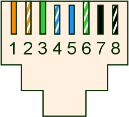
The RJ-45 connector should be mounted with the bare contacts up and the spring locking hook down. This helps keep dust off the contacts. Pin 1 is on the left as you look at a female socket, or on the right if you look at a male-ended cable end-on.
| Ethernet RJ-45 T568B Connector and Cable Pins | ||||
|---|---|---|---|---|
| Pin | Regular Ports | Regular Colour | Uplink Port | Crossover Colour |
| 1 | Input Receive Data + | orange solid | Output Transmit Data + | green solid |
| 2 | Input Receive Data - | orange striped | Output Transmit Data - | green striped |
| 3 | Output Transmit Data + | green solid | Input Receive Data + | orange solid |
| 4 | not used, possibly not even present | (blue) striped | not used, possibly not even present | |
| 5 | not used, possibly not even present | (blue) solid | not used, possibly not even present | |
| 6 | Output Transmit Data - | green striped | Input Receive Data - | orange striped |
| 7 | not used, possibly not even present | (black) solid | not used, possibly not even present | |
| 8 | not used, possibly not even present | (black) striped | not used, possibly not even present | |
According to David Charlap there is yet another reason. The center pins of RJ-11 and RJ-14 jacks are used to carry voice on single-line analog phones. It is possible to accidentally plug a phone into an RJ-45 jack. When this happens, you don’t want to run phone voltages into your Ethernet —you may damage it. It’s better to leave those wires unused.
Usually you buy cables that are way too long. What do you do with the excess? Coil it. Don’t just dump it in a heap. If you get 90 degree or tighter bends you will damage the cables and degrade signal quality.
It really doesn’t matter whether you use T568A or T568B when making patch cords, since they’re electrically identical. It can be important, however, when wiring up cables to the back of a patch panel. Usually, there is no easy way to see which attachment points correspond to which pins, so the attachment points are color coded according to one of the two standards. It doesn’t matter which you choose, but if you aren’t consistent throughout your network, you may find that patch cables connecting your patch-panel connectors don’t always work. (Customarily, T568A is used for commercial wiring and T568B for residential.)
It is also worth noting that although these pinouts are used for 10BaseT and 100BaseTX, there are other Ethernet standards as well. There is a 100BaseT4 standard (not common anymore) which uses all four pairs (allowing you to move 100Mbps (Megabits per second) without needing cables that can handle 100MHz signals). 1000BaseT (Gigabit Ethernet over copper) also uses all four pairs. Just to keep you on your toes, some other network interfaces that use RJ-45 include:
| RS-232C over RJ-45 | |
|---|---|
| pin | Purpose |
| 1 | DSR/RI |
| 2 | DCD |
| 3 | DTR |
| 4 | signal ground |
| 5 | RD (Receive Data) |
| 6 | TD (Transmit Data) |
| 7 | CTS |
| 8 | RTS |
Telephones only need two wires to work. You will sometimes see just a red/green pair of conductors. In older homes you will see three conductors red/green/yellow with yellow delivering the party line ring. In modern homes you will typically see four wires. The second pair are used when a home has two outside lines. To get at the alternate pair, you must wire a jack to access them in the usual line 1 positions (pins 3 and 4), or you need a 4-wire, two-line phone.
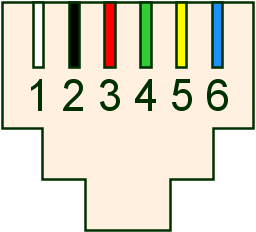
The RJ-11 connector should be mounted with the bare contacts up and the spring locking hook down. This helps keep dust off the contacts. Pin 1 should be on the left as you look at a female wall socket, or on the right if you look at a male-ended cable end-on. And of on the left if you look at a male-connector from the side where the cable comes out.
To make it easier to tell which side in pin 1 there is usually a ridge running down the underside of the outer insulating sheath. The RJ-11 connectors are transparent, so it is possible to tell if pin 2 has been connected to yellow or black by looking through the bottom of the connector.
| RJ-11 4-Connector and Cable Pins | ||||
|---|---|---|---|---|
| Pin | Shade | Colour | Polarity | Purpose |
| 1 | (white) | + | not used, normally not even present | |
| 2 | yellow | + | tip line 2 | |
| 3 | green | + | tip line 1 | |
| 4 | red | - | ring line 1 | |
| 5 | black | - | ring line 2 | |
| 6 | (blue) | - | not used, normally not even present | |
You will often find phone jacks wired with reverse polarity. You will also find wiring that flagrantly violates the colour code. Y This will cause unreliability and sometimes complete failure with some modems. You can test them with a voltmeter, or with a telephone tester from Radio Shack that just plugs into the RJ-11 outlet. Don’t try to poke your voltmeter probes directly into a socket. You will likely short them. You can make your own tester with a connector and a short piece of lead with the insulation stripped. It is a simple matter to correct the jack by reversing the screw-pole wiring inside.
You will often seen two sets of wires (for two lines) going to the same outlet. Pay careful attention to how the existing wiring attaches to the white, yellow, green red, black and blue wires inside the existing phone jacks.
The ringing voltage is 40 — 150 V RMS (Root Mean Square) AC, at 15.3 Hz (Hertz) to 68 Hz, superimposed on the normal DC voltage of 50 volts between tip and ring. You want to avoid shorting. Typically you work on phone cabling with live voltages. You need to watch out for these painful high ring voltages. Believe it or not, there was once an electrocution fatality from working on live phone lines. For safety, you can disconnect the parts of the circuit you are working on while you work on them and then connect them back to live voltages for polarity testing as you go.
The typical connecting cable between the wall and a telephone has two males ends, one end wired with pin 2 it a cross-over cable. However, not to worry, all the telephones and modems of the world are wired backwards to expect this. Cross-over cables are easily constructed. Just apply a connector the same way up on each end of an untwisted piece of cable, using the bottom ridge to guide you. No individual wires need to be twisted.
Just to keep you on your toes, some computer applications for RJ-11 connectors use straight through cables. To make one of these, apply one of the connectors to the other side of the cable.
Making phone cables in pretty easy. About all you can do wrong is create a straight-through when you needed a crossover or vice-versa, or fail to center the 4 wires in the 6-slot connector. Beware, there is also a narrow 4-conductor connector used between telephones and handsets. These are not designed to fit into the usual 6-conductor wall sockets. At first glance you might confuse the two since they both typically carry 4 conductors. Mistakes are easy and cheap to correct. Just chop the end off the cable and try again.
The crimping tool should come with diagrams and instructions on use. It is crucial you have a clean end cut. Any stray strands poking out could cause shorts. The crimping tool has a cutter. It should give you a nice clean square cut. If not, clean it up with some scissors.
When you crimp a cable two things happen:
You want the wires to poke all the way into their slots. The connector is transparent, so peek under a strong light from all angles to make sure you have the wires all the way in, aligned with the little brass knives. After you have done a few, you can tell by feel when you have it right.
Home crimping tools are rather delicate, so don’t squeeze down any harder than it takes to push the two arms together.
The outer brass contact hooks on the connectors often break off, leaving a flaky contact. You can be a minor hero by replacing those connectors wherever you find them in the universe.
Female RJ-11 connectors are not easily replaced. Usually they are soldered in place. The best you can do is clean the contacts — the wire springs. See my essay on contact cleaning/treating. You can use a foam swab or a toothpick soaked in isopropanol or DeoxIT to clean the contacts. They can get quite corroded and dusty. When you are done make sure you leave them nicely aligned. A bent one could cause a short. There is not much point in replacing all the male connectors and leaving the female ones filthy.
The connectors have three rows of pins in a D shape shell that plug into the back of the computer. The other end is usually hard wired into the monitor or attached via BNC (Bayonet Neill-Concelman connector) connectors. Here is what a male connector looks like pins facing toward you.
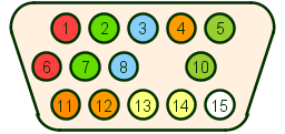
The pinouts are as follows:
| VGA 15-pin Connectors | |
|---|---|
| Pin | Purpose |
| 1 | Red analog Video |
| 2 | Green analog Video |
| 3 | Blue analog Video |
| 4 | Monitor ID Bit 2 for plug & play |
| 5 | Ground |
| 6 | Red return (separate ground) |
| 7 | Green return (separate ground) |
| 8 | Blue return (separate ground) |
| 9 | key, no pin |
| 10 | Sync return (separate ground |
| 11 | Monitor ID Bit 0 for plug & play |
| 12 | Monitor ID Bit 1 for plug & play |
| 13 | Horizontal Sync |
| 14 | Vertical Sync |
| 15 | unused, formerly data clock. |
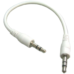 |
| mini audio loopback cable |
| Computer Sound Connectors | ||
|---|---|---|
| Colour | Shade | Purpose |
| grey | middle out | |
| black | subwoofer middle out | |
| orange | rear out | |
| pink | microphone in | |
| green | line out, front speakers | |
| blue | line in, connect tape player etc. input. | |
 |
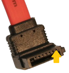 | ||||||||||||||||||||||||||||||||||||||||||||||||||||||||||||||||||||||||||||||
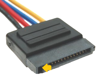
| SATA power cable | SATA data cable | ||||||||||||||||||||||||||||||||||||||||||||||||||||||||||||||||||||||||||||||
|
| ||||||||||||||||||||||||||||||||||||||||||||||||||||||||||||||||||||||||||||||
An AC wall outlet and corresponding power cord looks like this:
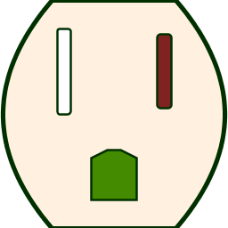
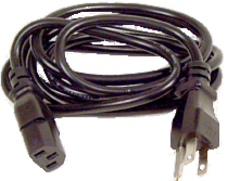
The larger left slot is neutral, the smaller right slot is hot. The central bottom hole is ground. Inside the box, neutral is wired to white, hot to black (rarely red), and ground to green or bare copper. Amateur astronomers might remember which slot is hot by recalling that small stars are usually hotter than large ones.
Some plugs have three prongs and can go in only one way. Some have two, with one prong wider than the other. They two can go in only one way. Some older plugs have two small prongs. They can go in either way.
Lamp sockets are designed so the center contact is hot and the outer rim is neutral. This reduces shock hazard should you change a bulb with the power on.
Switches should either make/break both hot and neutral or failing that make/break hot. It is unsafe to have a switch that make/breaks neutral only since then there are live voltages inside the device even when the power is switched off.
Basically your job is just to keep connecting black to black, white to white and green to green. Hot is represented by brass colour and neutral by silver colour on screw posts in wall sockets and lamp sockets. Be careful to prune stray frays of wire least they touch and short.
Using an AC voltmeter you can easily test that socket polarity is correct vis a vis hot/neutral, though I don’t know how you would easily detect crossed neutral/ground. That is less likely. You can get AC socket testers at hardware stores.
The ground wire protects you this way. If for example a fault in a 3-wire toaster put live voltage on the case, since the case is attached to ground, it would short immediately and trip the circuit breaker, turning everything off before anyone got seriously hurt. Without a ground, the case could be live without tripping the circuit breaker.
Life gets much more complicated wiring up a power supply to a switch. You are breaking the current both on the way in and the way out of your power supply. There you have four wires black, white, brown and blue. The switch acts like two switches, one to break the black to brown hot side and one to break the blue to white returning neutral side. Inside the machine, past the switch, brown is hot and blue is neutral. Breaking both hot and neutral helps protect you from idiots who wire up AC outlets backwards. You can test your switch with a continuity meter to figure out how it works. From that you can figure out which wire should go where. Think a long time and triple check. There are many ways to do it wrong that create a puff of smoke.
Final hint. Never do work on AC wiring with anything plugged in, including power supply switches.

![]()
![]()

If you are designing new protocols, connectors and cables, see if you can avoid some of the errors of the past:
Building your own cables sounds much more complicated than it is. You can do it much faster than I can describe it. Consider that I am one of the most mechanically inept people around. I made cables successfully all the time. I give so much detailed advice because I imagine I am talking with someone like myself with little mechanical intuition.
Basically all you do is cut your cable squarely, thread the connectors squarely, and squeeze.
I know longer have my cable workshop, so I can no longer build or repair cables for you.
This page is posted |
http://mindprod.com/bgloss/cables.html | |
Optional Replicator mirror
|
J:\mindprod\bgloss\cables.html | |
Please read the feedback from other visitors,
or send your own feedback about the site. Contact Roedy. Please feel free to link to this page without explicit permission. | ||
| Canadian
Mind
Products
IP:[65.110.21.43] Your face IP:[216.73.216.202] |
| |
| Feedback |
You are visitor number | |